| Turner Sports Cars | Articles |
| Turner Sports Cars | Articles |
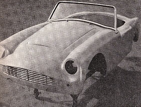
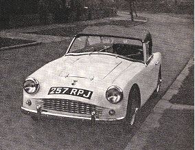
| Ashley Clarke describes and illustrates how he and a friend built one of these glassfibre-bodied sports cars in a hundred hours of their spare time. The car has an Alexander-modified 948 cc B.M.C. engine, and front disc brakes. |
| "Why not build your own sports car ?" At first, the idea seemed ludicrous. But the more the two of us thought about it, the more we took to it. Eventually, it was not ludicrous, but entirely practical.
We had a working mechanical knowledge and a full range of tools - nothing special, but all the normal garage equipment an enthusiast would have. And the makers said we would not need any more. One important point we considered before undertaking this work was that of insurance. There are a number of insurance firms who will undertake the risk when home assembly is under consideration, but it was worth inquiring both of the manufacturers and an insurance broker to get the best possible quotation. Whilst on this, perhaps reference ought also to be made to the inspection made by the taxing authorities after the car was built. This was necessary before they issued the log book, but no difficulties were encountered. It took five hours to get the car on its wheels, 30 hours to reach the stage when the engine fired, and 100 hours to complete, excluding painting. During this account of the work, no more than passing reference will be made to greasing and cleaning every part as it was assembled. But this, of course, took place and was essential. After taking delivery we first sorted out all the items and removed the body from the chassis frame. These two items were tack bolted together at Turner's works so as to ease the question of transport.
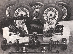
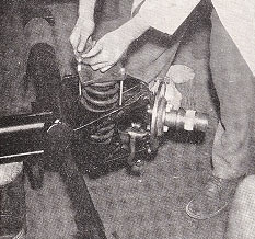
Having placed the chassis on a pair of trestles approximately a foot high we proceeded to assemble the front suspension units first. These are attached to the chassis by three bolts, two on the lower link and one on the top of the steering pin yoke. Having squeezed the tapered rubber bushes into their housings the holes were lined up with 3/8-inch diameter bar and the bolts tapped into place. After all the bolts were in, these were finally tightened up and the chassis turned upside down to that we could fit the front coil springs. These needed compressing considerably and it was necessary to obtain two 4½-inch by 5/16-inch bolts threaded right the way down. By placing these in opposite corners of the holding plate the spring could be wound in by screwing up these bolts a little at a time. When the spring seat was nearly home the correct bolts were put in and tightened up. The chassis was now turned over again and the steering rack-and-pinion unit bolted to the bracket with the clamps provided and finally the outer ends attached to the steering arms.
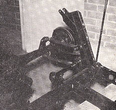
The next operation was to bolt the rear axle and the Panhard rod into position. This was a straightforward operation. Next the handbrake cables were fitted and coupled up and finally the flexible hydraulic brake pipes were attached to the rear axle and front brake calipers and the whole brake pipe system tightened up - not forgetting the copper washers on the ends of the flexible pipes.
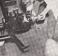
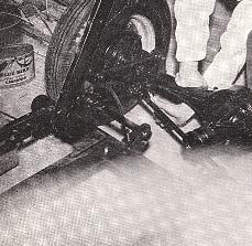
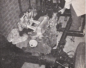
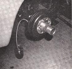
When tackling the flexible brake pipes, we secured the pipe end nearest the wheel first in the case of the front wheels. On the back, we had to undo the metal pipe and locking nut, fix the flexible pipe into the junction and then reassemble the other end. The hand-brake cable was next put on - over the top of the Panhard rod. There were two supports for each wire, one on the chassis just behind the triangular weld and the other on the rear of the back axle. We had disc brakes fitted to the front wheels, together with wire wheels and these were fitted to the hear hubs with an adaptor. When the adaptors were fitted, using specially shortened wheel nuts, the surplus length of wheel stud had to be cut off otherwise the wheel would not have seated on its taper properly and we would have been liable to loose a wheel. Before we put the engine in, we went round all the grease nipples, tracked the wheels using the simple directions in the handbook, roughly cut out the rear-light panels and stuck the dashboard leather cloth on with Bostik C - now known as Bostik 2. Dropping the engine into the chassis was tricky. The entire engine, gearbox and clutch unit went in at once - and it was heavy ! We set the bearers for both engine and gearbox loosely on their brackets on the chassis and then lowered the whole unit on to them. Immediately everything was bolted up loosely, we put the prop shaft on - after greasing, of course - engine end first. Then, when the rear axle/propshaft bolts were also loosely secured, we tightened up all round - from engine mountings to rear axle. The transmission was then complete.
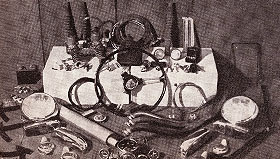
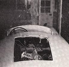
We were next faced with a mass of mass jobs. They could be done in any order so long as they were completed before the body went on. None took very long. We fitted the rev counter gearing unit to the dynamo. We put the pedal unit into place and bolted it up, and we also secured the fuse box and cut-out unit on the side of the pedal unit as well. This saved a lot of time and fiddling later on. Unless we had had four strong pairs of arms available, we would have been foolish to attempt fitting the body to the chassis without the aid of pulley blocks. It was no light weight and had to be manoeuvred carefully. First of all, we lightly taped the wooden struts onto the rear supports - they were there when we took the body off. Careful not to foul the transmission tunnel with the gear lever and handbrake, we then eased the body on. Finally, it slid into place; and "it" was beginning to look like a car. We bolted up all round, fitting the rear shock absorbers at the same time. Again, we had to force the rubber bushes into place using the long thin screwdriver technique we had developed to deal with the wishbone bushes on the front suspension.
The exhaust system was the next job. It was also one of the most straightforward. We had to build up the outside nuts on the exhaust manifold with washers, but the inside nuts did not need this treatment. The silencer was fixed by a Jubilee clip at the manifold end and a rubber junction at the other. The steering column went in next, being bolted up first at the union between column and rack. The locking nut only went on correctly one way, when the splines were seated properly on the steering arm. This was not at the bottom limit but a third of the way up. As soon as we had got the correct angle for the steering arm, we tightened up the bolts on the chassis which hold the rack itself. We then bolted the universal joint half way up the steering arm onto the scuttle. We drilled holes for this. The pedal unit and hydraulic pipes came next. The two longer pipes were bent from the brake pedal pump to the brake system inlet on the chassis, and from the clutch pedal pump to the pipe from the clutch housing - meeting at the bracket on the scuttle. We also put the brake light unit on the brake system. After we had secured the master cylinder to the scuttle - which meant putting the battery in at the same time so that both units had enough room - we connected the other two pipes from the pedal pumps to the master cylinder. We then had to bleed both clutch and braking systems, constantly topping up the tank and bleeding one outlet at a time: first the clutch, and then all four brakes. Brake and clutch adjustments came later.
The petrol tank was put in and the fuel float and fuel pipe connected up. The fuel pipe ran along the chassis on clips already fitted but we later changed this to take the pipe along the other chassis member so that the fuel was on one side of the car and the exhaust on the other. At this point the car was towed away for spraying. When we got it back we did several jobs which could have been done before spraying. Connecting the water pipes for instance. Here we also introduced our own modification. The elbow junction for the pipes from engine to radiator was fixed on the scuttle over the near-side front wheel housing. The heater outlet was also introduced at this junction, instead of into the pipe itself. This needed welding equipment, which is unnecessary when building the car normally. We cut the dashboard holes and fitted the instruments and switches. This was straightforward, although we found the wiring diagram essential. A means of finding the circuits electrically would also have been a help, but we didn't have one. The dials were simple - oil pressure pipe to engine, rev. counter to dynamo, speedo to gearbox, temperature gauge to radiator - taking their lines through the steering column hole. The petrol and ammeter dials were both on the wiring circuits. Wiring was done one unit at a time. We put the lights into the body and wired them, then the ignition system and so on. During the wiring of the ignition, we decided to shift the petrol pump across to the off side of the car. It was then we moved the fuel line. When all the wiring was complete we were ready to fire - and she did. But there was a lot more to do - finishing off, details . . . Everything was checked, the car tracked again, (following the directions in the handbook, brakes and clutch adjusted, steering checked, full lubrication and oil checks throughout. Then came the trim. Again we used Bostik 2. We did the job surprisingly quickly. We stuck the back panel first, then the side panels, and the half-side panels. Then the carpets went in, plus a heavy underfelt - another extra of ours - and finally the seats were bolted in. Trimming the doors was more tricky, for we had to cut the panels out. Windscreen wipers, bumpers, radiator grille - slightly bowed for effect - hood and sidescreens and we were nearly home. The hood press-stud fasteners were awkward. They had to be absolutely right to keep the hood taut. And bending the side screen supports - on the sliding sidescreens we had - was also tricky for the same reason. We also put the nameplates and conversion tags on, again using Bostik. There was only one other job before the car was complete. Rubber cushioning was put around the boot and bonnet edges - after we had cut the width supplied in half - and the bitumen compound sealed the shock absorber covers in the boot and also the edges between glass fibre and metalwork under all four wheel housings. This final job was important. Failure would have meant water being sprayed in and setting up rust where it was totally inaccessible. As we had wire wheels, we also had to check that the cutting of the nuts on the rear hubs was absolutely flush. This was of paramount importance, since failure to make sure the rear wheels sat absolutely flush could have meant a wheel flying off at speed. We should have raised the jacking bolts on the rear of the chassis but we left it until the car was run in and settle, as is done normally. But this car was exceptionally low and it should have been done earlier. Building this car was quite an experience, and a triumph. We know every nut and bolt on it, and almost every characteristic it has both on the road and in the garage. Would we do it again ? Certainly. Early in the running-in period it became apparent that the ignition system was not all it might be. Despite the careful tuning and the fact that everything was brand new, response to the accelerator was not really satisfactory. Consequently the car was subjected to a Crypton-tune which revealed that minute improvements were essential if we were to get the manimum performance out of this car. The running-in period revealed two other factors. Firstly, we discovered that the Alexander super sports camshaft which we had fitted was such a critical piece of engineering that the cam-followers would take some time to settle down. Consequently, the tappets had to be kept under constant watch. We found that the KLG FE220 plugs which had been recommended undoubtedly gave maximum performance, but were liable to oil up in average motoring conditions. It thus seemed necessary to fit a softer plug for ordinary motoring and leave the 220s for rally work, or hard motoring on the M1. Apart from its remarkable acceleration and unusually smooth gearbox, this car's outstanding characteristic seems to be its handling. Even under the wettest conditions it shows no inclination to move off the line it has been set round any corner. The makers' claim that this is a 40-mile-to-the-gallon-sports-car seems absolutely valid. In fact, during the running-in period we got the best part of 50 miles to the gallon over a thousand miles. Even now, as the car is reaching it peak performance, having just been fully run-in, the consumption is well up to 40 taking an average over town and country driving. In short we think the Alexander-Turner is a splendid little car. It is safe to handle and the firm suspension and remarkable twin-tubular chassis give the car a feeling of tautness and precision not felt in any other car we have driven. It is safe, fast, and reliable. Once we had overcome the teething trouble inevitable with such a piece of precision engineering it quickly proved that it had been well worth building.
|